Products
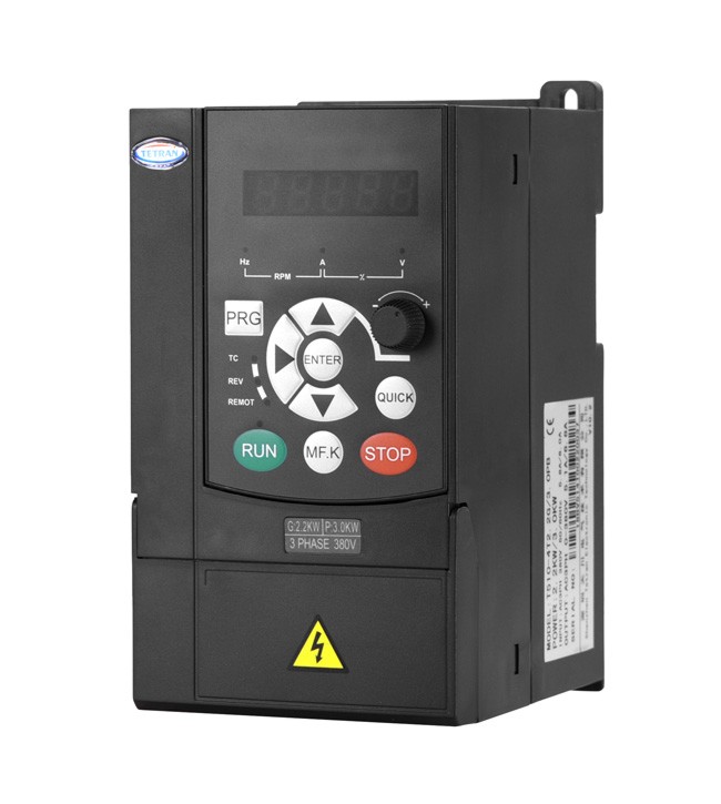
T510-WF22 series reciprocating spraying machine special inverter...
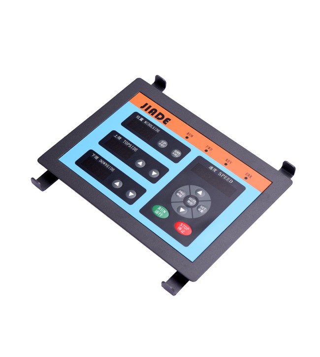
Reciprocating Spraying Machine
●Save PLC and controller, realize position control and save cost for customers.
●Special display panel can display position signal, upper and lower limit signal and speed signal.
|
Code |
Name |
Setting Range |
Default |
Alteration |
|
F0 System Management Parameter Group |
||||
|
F0.02 |
User password |
0~65535 |
0 |
|
|
F0.03 |
Parameter protection setting |
0:All data can be modified 1:No modification except for this function code and F0.02 |
0 |
|
|
F0.06 |
Parameter initialization |
0:Misoperation 1:Factory reset 6:Backup user current parameters 888:Restore user backup parameters |
0 |
|
|
F0.07 |
Application macro of reciprocating spraying machine |
0:Invalid 1:2m stroke 2:2.5m stroke 3:3m stroke 4:3.5m stroke 5:4m stroke |
3 |
|
|
F1 Basic Function Parameter group |
||||
|
F1.16 |
Acceleration time 1 |
0.00S-65000S |
0.5 |
|
|
F1.17 |
Acceleration time 1 |
0.00S-65000S |
0.5 |
|
|
FA Auxiliary Function Parameter Group |
||||
|
FA.03 |
JOG running frequency |
0.00-maximum frequency |
12.00 |
|
|
FA.04 |
JOG acceleration time |
0.00S-65000S |
1.0 |
|
|
FA.05 |
JOG deceleration time |
0.00S-65000S |
1.0 |
|
|
A2 Special Functional Parameter Group of Reciprocating Spraying Machine |
||||
|
A2.00 |
Workpiece lower limit setting |
0 ~ A2.01 |
0 |
|
|
A2.01 |
Workpiece upper limit setting |
A2.00 ~ 1000 |
1000 |
|
|
A2.02 |
AI input selection |
0:AI1 1:AI2 |
0 |
|
|
A2.03 |
Workpiece minimum |
0 ~ 1000 |
100 |
|
|
A2.04 |
How much is the upper limit of workpiece distance to start frequency reduction |
0 ~ 500 |
100 |
|
|
A2.05 |
How much lower limit of workpiece distance starts frequency reduction |
0 ~ 500 |
100 |
|
|
A2.06 |
Upper bound frequency reduction |
0 ~ 100% |
100% |
|
|
A2.07 |
Lower bound frequency reduction |
0 ~ 100% |
100% |
|
|
A2.08 |
Forward and reverse dead time |
0.0s ~ 3000.0s |
0.0 |
|
|
A2.09 |
Bottom dead center of AI analog quantity |
0.00 ~ A2.10 |
2.20V |
|
|
A2.10 |
Top dead center of AI analog quantity |
A2.09 ~ 11.00V |
6.80V |
|
|
A2.11 |
Maximum deceleration inertia |
0.00 ~ 5.00V |
1.80V |
|
|
A2.12 |
Upper limit maximum alarm |
5.00 ~ 10.00V |
10.00 |
|
|
A2.13 |
Lower limit minimum alarm |
0.00 ~ 5.00V |
0.00 |
|
|
A2.14 |
Undervoltage point setting |
75.0% ~ 140.0% |
100.0% |
|
|
A2.15 |
AI input actual value |
0.00 ~ 10.00V |
Actual value |
|
|
A2.16 |
Height coefficient |
0.000 ~ 65.535,Actual height (m)=F2.16*F2.15 |
1.000 |
|
|
A2.17 |
Power on and stop display initial screen (monitoring parameters) |
0:Set frequency 1:Bus voltage |
0 |
|
|
A2.18 |
Power on operation display initial screen (monitoring parameters) |
0:Operating frequency 1:Set frequency 4:Output current 5:Height value |
0 |
|
|
A2.19 |
Reserved |
|
|
|
|
A2.20 |
Selection of upper and lower limit changes in operation |
0:Modified 1:Unmodified |
0 |
|
Transducer is the size of T510
Operation panel: 185 x 131 (mm)