Products
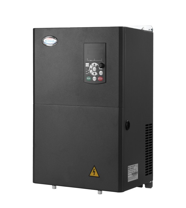
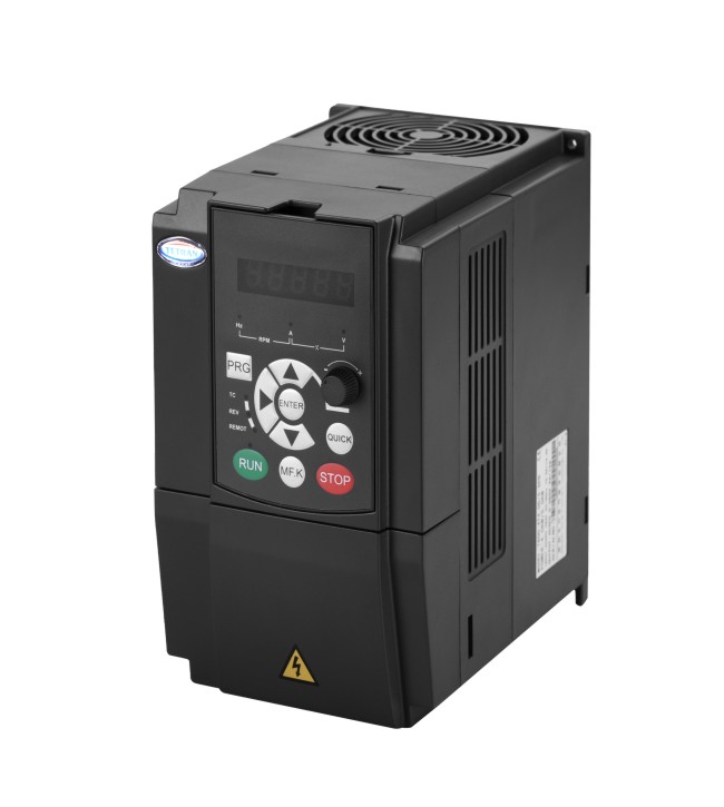
Carving Machine Special Inverter...
Carving machine
•Adopt 32-bit DSP special control chip, voltage space vector SVPWM control.
•Arbitrary setting of carrier frequency 0.7-16khz(if the carrier frequency cannot be adjusted too low, overcurrent protection may occur if it is too low).
• Maximum frequency up to 3200hz.
•It has synchronous and asynchronous modulation functions.
•With the application macro of engraving machine, customers can set two parameters to meet most of the requirements of engraving machine parameter setting.
The CNC engraving machine requires the spindle system to adopt stepless speed change. At present, the frequency converter is mostly used to drive the asynchronous AC motor. The spindle motor mostly adopts two pole high-speed brush free water-cooled motor, which has low noise and large cutting force. The general engraving machine generally operates at a speed of 0-24000r / min, the corresponding frequency converter operates at a frequency of 0-400hz, and the precision engraving machine also operates at a speed of 48000r / min. With the advantages of 0-3200hz speed regulation range, high speed stability, strong overload capacity, large low-speed torque and short acceleration and deceleration time, widely used in carving machine market. According to the different given modes of frequency source, it can be divided into the following two types:
1. The frequency source of the spindle is the mode given by the analog quantity
The frequency source of the frequency converter adopts the 0-10V analog signal output by the numerical control system, and the corresponding operation frequency is 0-400hz. This method can realize stepless speed regulation for the spindle, and change the spindle cutting speed in real time according to different carving objects or carving processes. It is widely used in medium and high-end engraving machines with high requirements of carving technology and fine.
2. The frequency source of the main shaft is the given mode of multi-stage speed
According to the machining process requirements of the engraving machine, the user sets multiple operating frequencies of the spindle in the converter parameters in advance. When the CNC system needs different spindle frequencies, the multi-channel digital signals output by the engraving controller can set the operating frequency according to the frequency converter corresponding to the preset combination mode, which can quickly respond to the spindle speed in the engraving program written by the user To achieve the best effect. The spindle operated in this way is not stepless speed regulation, and can only operate a fixed number of frequencies. It is generally used in occasions with low carving technology requirements and low-end carving machines.
|
Code |
Name |
Setting Value |
Note |
|
F0.02 |
Command source selection |
1 |
|
|
F0.03 |
Main frequency source x selection |
6 |
|
|
F0.08 |
Preset frequency |
400 |
|
|
F0.10 |
Maximum frequency |
400 |
|
|
F0.12 |
Upper limit frequency |
400 |
|
|
F0.15 |
Carrier frequency |
400Hz:6K 800Hz/1000Hz:12K |
According to the maximum frequency |
|
F0.22 |
Frequency command resolution |
1:0.1Hz |
|
|
F1.04 |
Rated frequency of motor |
400 |
Motor’s nameplate |
|
F1.05 |
Rated speed of motor |
24000 |
Motor’s nameplate |
|
F3.02 |
Torque up cut-off frequency |
400 |
|
|
F4.00 |
X1 terminal function selection |
1:Forward |
|
|
F4.01 |
X2 terminal function selection |
2:Reverse |
|
|
F4.02 |
X3 terminal function selection |
12:Multi-segment command terminal 1 |
|
|
F4.03 |
X4 terminal function selection |
13:Multi segment command terminal 2 |
|
|
F4.04 |
X5 terminal function selection |
14:Multi segment command terminal 3 |
|
|
F4.13 |
Ai1 min input |
0.5 |
|
|
F4.15 |
AI1 max input |
9.90 |
|
|
F7.02 |
|
|
|
|
F7.03 |
LED operation monitoring selection 1 |
401d |
|
|
F7.06 |
Load speed display factor |
600 |
|
|
FC.01 |
Reference1 |
25.0% |
|
|
FC.02 |
Reference2 |
37.5% |
|
|
FC.03 |
Reference3 |
50.0% |
|
|
FC.04 |
Reference4 |
62.5% |
|
|
FC.05 |
Reference5 |
75.0% |
|
|
FC.06 |
Reference6 |
87.5% |
|
|
FC.07 |
Reference7 |
100.0% |
|
T600-DK